Introduction
The 3DM-CV7 supports user-configurable "events" which can trigger transmission of data or change the state of a GPIO pin. They can be triggered from a variety of sources including data quantities and GPIO inputs. These events are highly flexible and can reduce the bandwidth, processing, and power requirements of the system by only transmitting data when it's needed.
The event system can also be leveraged to provide real-time synchronization between systems. For example, it could be used to generate attitude and heading information that is synchronized to a camera's shutter.
Details about timing accuracy and latency of event system components can be found in Timing.
Event Components: Triggers & Actions
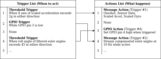
An event consists of two components: a trigger and an action. Actions define what should happen, while triggers define when it should happen. The device maintains a list of triggers and a list of actions. Each trigger or action is referenced by a number called the instance id. The id represents its position in its corresponding list (see figure below). Actions are linked to triggers by a trigger id field which is set to match the instance id of the trigger.
For example, an action might be configured to emit a MIP data packet, and a trigger might be configured to detect acceleration exceeding a threshold. The configuration is outlined in the figure below. The threshold trigger (trigger id = 1) sends a MIP data packet (action id = 1) when the acceleration exceeds 2g.
An action can be activated by any trigger, and more than one action can be activated by the same trigger. The actions must simply reference the id of the correct trigger.
Types of triggers
- None - Does nothing. A trigger set to None will never activate and cannot be enabled.
- Trigger: GPIO - Watches the state of a GPIO input pin. It can activate while the state is high or low, or on a transition. The edge detection mode can be used for precise timestamping and synchronization.
- Trigger: Threshold - Watches a specified data quantity. It can check if the value is within or outside of a user-defined window. It can also trigger on time intervals (e.g. every second).
- Trigger: Combination - A logical combination of up to four other triggers.
Types of actions
- None - Does nothing.
- Action: GPIO - Controls the state of a GPIO pin set to output mode. Useful for triggering external devices.
- Action: Message - Sends a MIP message containing user-specified data quantities. It uses a message format similar to regular data streaming.
Activating Events
Triggers are "active" when the specified condition is met. This depends on the type of trigger and its configuration parameters. An action linked to an active trigger will be executed. In the above example, if the z-axis acceleration is 3 g (i.e. more than 2 g), the trigger will be active and a MIP message will be emitted.
A trigger remains active as long as its conditions are satisfied. If the event in the example had been configured to send packets at 100 Hz instead of once, it would continue to do so as long as the acceleration stayed above 2 g.
Triggers must be enabled in order to become active. See the configuration section below for more details.
Oneshot vs. Continuous Components
Some components can be configured for either oneshot mode or continuous mode.
- Most triggers operate continuously. Actions are executed as long as the trigger remains active.
- The GPIO trigger, if set to "edge" mode, will only activate for one event cycle each time the pin changes state. Associated actions will execute once for each occurrence, but not more often than once per event cycle. Each pin state transition counts as a new activation, as if the trigger was deactivated in between.
- The Message Action has a decimation parameter which controls the rate at which packets are transmitted. When used with a continuous trigger, data is streamed while the trigger is active. If decimation is 0, only one packet will be emitted per activation; the trigger must reactivate before another packet will be sent.
Event Cycle
During an “event cycle” or “event tick” all of the configured triggers and actions are updated. Triggers are updated first, before any actions, because actions depend on the trigger states. Actions can be executed at most once per cycle.
The event cycle occurs at the base rate for the System Data descriptor set (0xA0). See Protocol Support and Specifications. With the exception of a GPIO trigger on a timestamped pin, trigger data is sampled at this rate.
Configuration
The event system is configured through MIP commands. The following provides a description of the relevant commands.
Trigger & Action Configuration
By default, all trigger and action instances are assigned the None type, which does nothing. The user can change this using the Event Trigger Configuration (0x0C,0x2E) and Event Action Configuration (0x0C,0x2F) commands. These commands require the user to specify the instance id, the type of trigger or action, and some parameters which depend on the trigger or action type. Actions additionally require the trigger id with which to be associated. The values for the ‘type’ parameters are listed in the documentation for the respective setup command.
The device reports what types of events are supported via the Get Supported Events (0x0C,0x2A) command. Device resources are limited, so this command also identifies the maximum number of instances of each component. This information is also provided in Protocol Support and Specifications.
Enabling & Disabling Triggers
Each trigger can be enabled, disabled, or placed into test mode using the Event Control (0x0C,0x2B) command:
- Disabled - The trigger will never activate.
- Enabled - The trigger performs its specified function.
- Test - Like disabled, but the trigger is forced to the active state. This is useful to test if an action is properly configured and linked to the right trigger.
- Oneshot - This setting puts the trigger into test mode for exactly one event cycle, after which it returns to its original setting (either enabled or disabled).
By default, triggers are disabled after configuration. Once configuration setup is complete, use the event control command to enable them. Trigger instances set to None cannot be enabled.
Event Status
Both triggers and actions have a command to get the status of one or more instances. This is useful to produce a summary of configurations and to verify the configurations.
Action status is obtained with the Get Action Status (0x0C,0x2D) command. The response identifies the type of each action and its associated trigger.
Trigger status is obtained with the Get Trigger Status (0x0C,0x2C) command. The response identifies the type of each trigger, whether it’s enabled, disabled, or in test mode, and if it’s currently active.
Both commands take an optional list of instance IDs to query. If the list is empty (the count field is 0), then all supported instances are returned. The response is a list with entries in order corresponding to the requested instance IDs.
Examples
All of the examples assume the device has been reset to the factory default settings.
- Synchronizing Data Output with an External System
- Gated Data Streaming using a GPIO
- Synchronized Square Wave Output
- Stopping a Robot if It Tips Over
- Advanced: Using Two GPIO Actions in Oneshot mode (Hysteresis)
- Advanced: Using a Latching Combination Trigger for Hysteresis
- Advanced: Using Two Thresholds with a Combination Trigger
- Troubleshooting Events